Eight Segment Display
Hey everybody, Ralph here.
So, I’m thinkin’ about a project that uses segmented displays. But the ones you get from the store are either old fashioned or way too complicated.
See, most of them take 1 input per segment plus either a common ground or power. They also produce only 1 color. Now, they come in a lot of colors but you still have to pick one and I find that a bit boring.
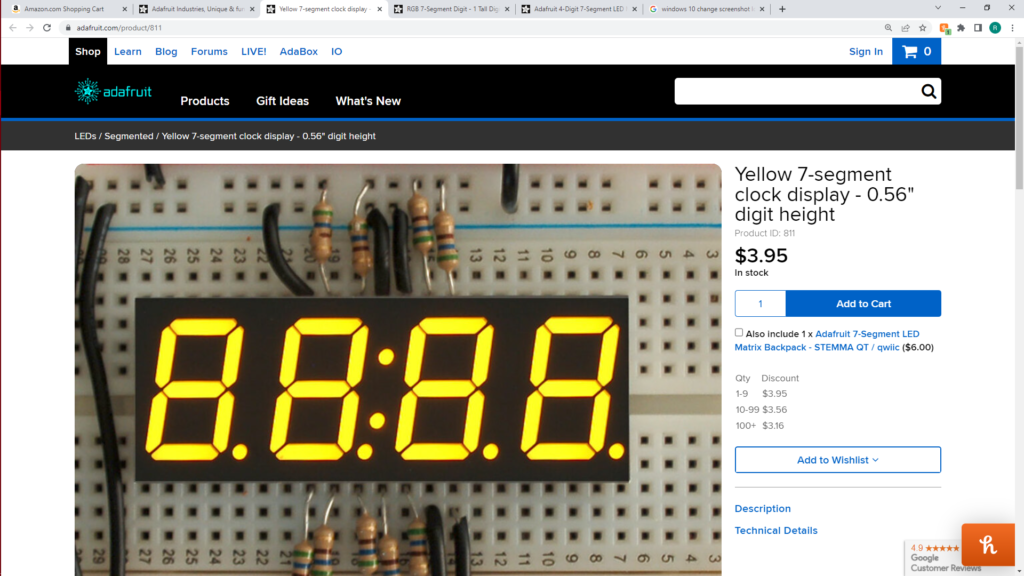
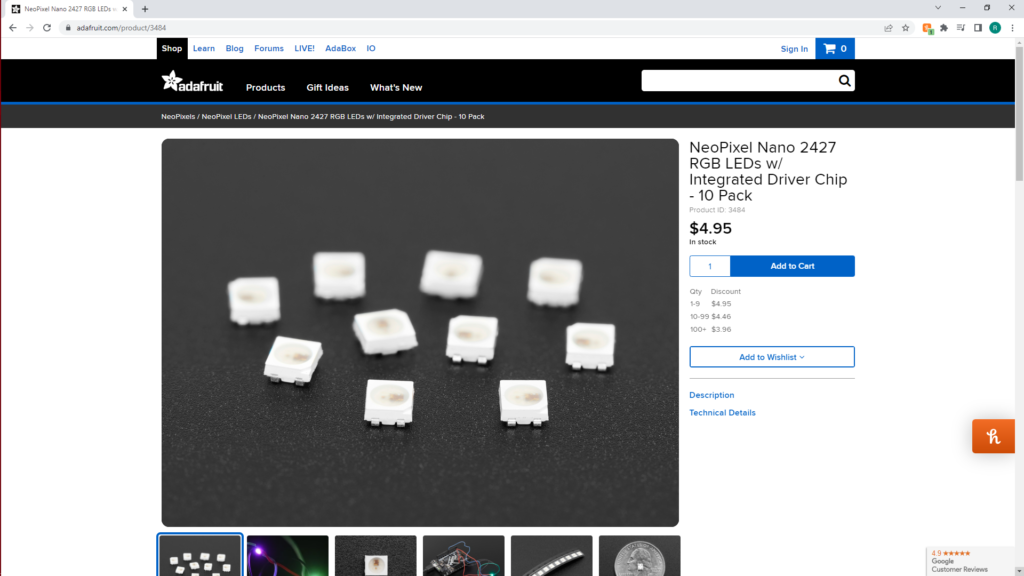
Adafruit does have this one but just look at all those inputs!
Nope I want more. Or, well, less. We live in the 21st century and I want a 21st century readout. I want any color at any time. I only want to deal with 4 pins maximum. I want to be able to chain as many together as needed and I want to make them myself. Well, that last part is a lie. I’d much rather just order them.
Fortunately the fine folk over at Adafruit have a possible solution if we want to put in a little effort to put it all together.
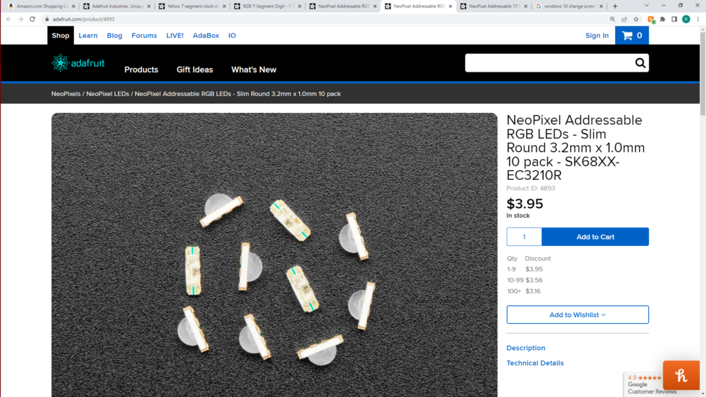
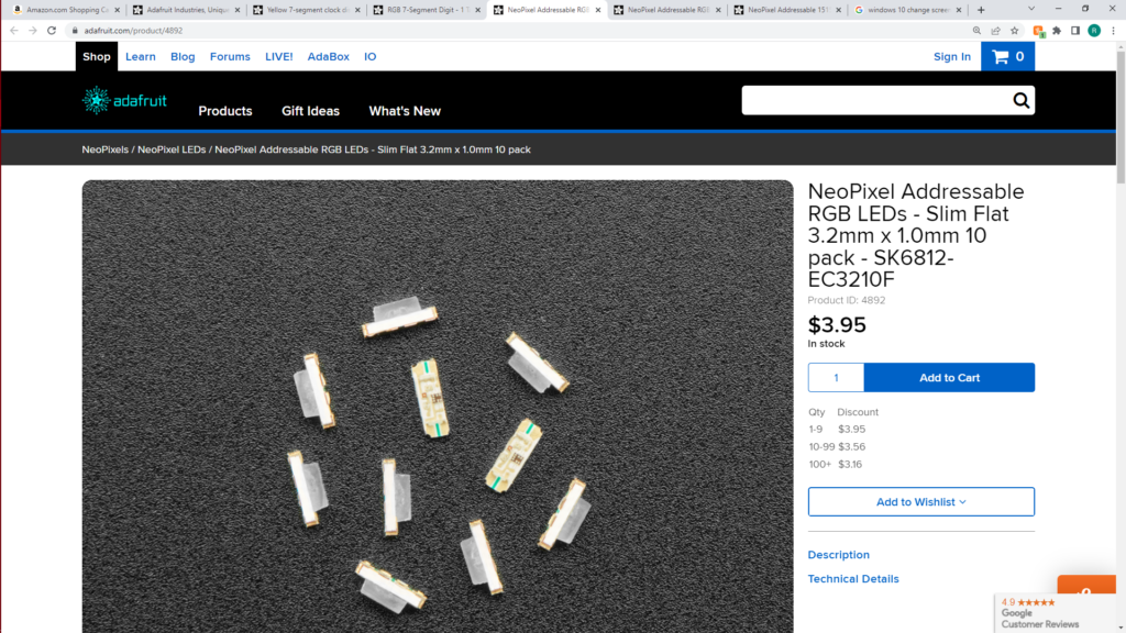
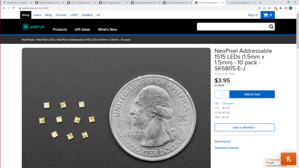
I just love these little neopixels. I wish everything was as easy to use. As you can see they come in a fair variety of sizes, shapes and configurations. I have a variety on hand. For this project I chose to try out these three but I had to change out the little fella as my old eyes couldn’t make out where pin 1 was and although they aren’t too expensive, after the 3rd attempt I decided to cut my losses and start over.
I ended up using the 2427 or 2.4mm x 2.7mm ones. They are bigger than I’d like but way easier to use. I’ll share the files for both so be careful when picking which one to get made.
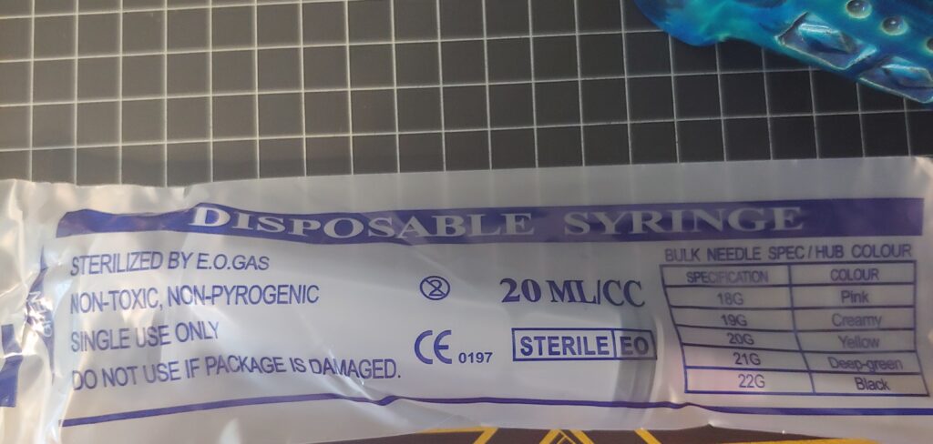
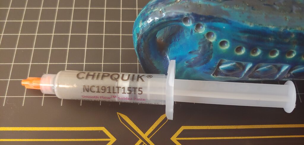
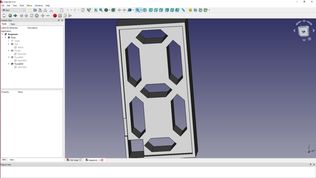
Now, this project is pretty straight forward but not without it’s unique issues. Besides changing out the tiny neopixel I also had to get some finer solder paste as what I was using was having issues. Solder paste comes in fineness from 1 to 4 and I usually use 2 but got some 3 for this project and it works much better. Thanks again Lady Ada as hearing you talk about the process in a recent show reminded me that other sizes exist. The 3D printed shell is still not quite right and the process for filling them with epoxy needs work. I ordered 20ml syringes with real sharp tips which I almost immediately stuck into the tip of my finger and 10ml would have been better. They make 10ml with blunt tips by the way. I also would have used more pigment as the mix I used is still too transparent. I have to say that the napkin made the best diffusor with the transparent 3D printed one coming in second so if anyone makes some of these and comes up with a better diffusor please post below.
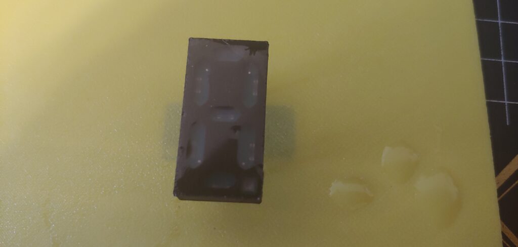
But, all in all they turned out passable.
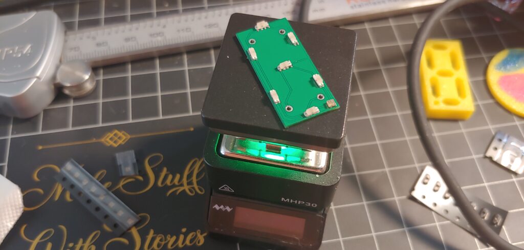
I designed the boards in DipTrace and the shell in FreeCAD then had the boards made at PCBWay. I use a modified Ender 3 v2 for the 3D printing and a Miniware mhp-30 for the reflow soldering, #notsponsored. I’m not recommending you use any of these, just sharing what I used for this project.
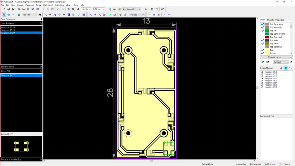
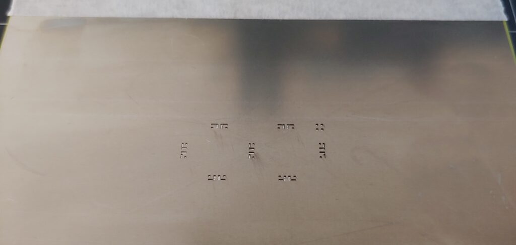
I ordered a stencil with the boards as I find that works better for me but I have seen folk place smaller parts than these by just depositing some paste right from the tube onto the board. The stencils don’t cost a lot but between them and the extra shipping you could save some cash if you don’t really need them.
I found out just how short my attention span really is when placing the long neopixels. I didn’t see any markings on the top so I flipped them upside down to check the pads but often forgot which way they were in the time it took to flip them right side up. Anyway.
There are lots of ways to reflow solder and lots of resources on the internet to learn more about them. If you end up with one of these cute little things be very careful as even after you turn it off the top stays extremely hot.
Once I got the boards assembled and tested I put them in the shells and ran some glue around where the board meets the shell and got most of them sealed. One had a small leak where some epoxy came through the bottom. I used some white pigment but was afraid to use too much so ended up using way to little. After mixing it up I poured it into the syringe and used that to deposit the epoxy into the shells. I tried to do a flood coat on the top and would see if I could make a wall around to perimeter the next time to make that easier.
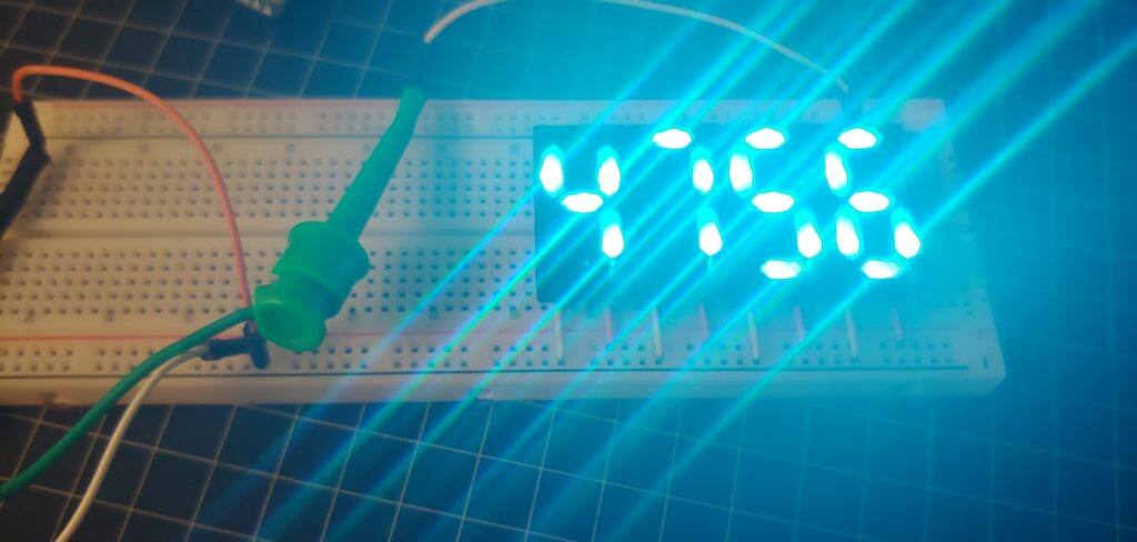
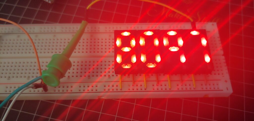
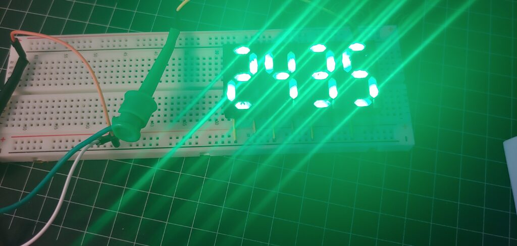
Once they had cured it was time to test them. As you can see in the code in the description below they are super easy to use. There needs to be more error checking but they work really well.
One issue I ran into was counting by tenths, .1 + .1. I haven’t done a lot of programming in the last 30 years but I would have thought that someone would have figured out how to do it right on a digital chip by now without making the poor programmer work so hard. See, when you are dealing with floating point math on a digital device it won’t always give the expected result. In this case when it got so far along instead of getting, say, .8 it would give .7999999 and cause an error. Since this was just a test I didn’t bother putting in the check and correction code.
So, they work, are super easy to wire up and use and look okay for a first try. With any luck by the time I get around to using them a company will have started making and selling an improved version.
import time
import board
from rainbowio import colorwheel
import neopixel
red = (255, 0, 0)
yellow = (255, 150, 0)
green = (0, 255, 0)
cyan = (0, 255, 255)
blue = (0, 0, 255)
purple = (180, 0, 255)
black = (0, 0, 0)
pixel_pin = board.GP0
num_pixels = 32
segs = 4
pixels = neopixel.NeoPixel(pixel_pin, num_pixels, brightness=0.3, auto_write=False)
def eseg(segs, color, tval):
tdigs = str(tval)
tlen = len(tdigs)
tdec = tdigs.find(“.”)
if tdec > 0:
trdigs = tdigs.split(“.”)
tdigs = trdigs[0]+trdigs[1]
tlen = tlen – 1
tarry = [“11111010″,”10000010″,”11011001″,”11001011″,”10100011″,”01101011″,”01111011″,”11000010″,”11111011″,”11100011″,”11111110″,”10000110″,”11011101″,”11001111″,”10100111″,”01101111″,”01111111″,”11000110″,”11111111″,”11100111”,]
c = 0
for i in range(tlen-1,-1,-1):
t = int(tdigs[i])
if i == tdec-1:
t = t+10
xt = tarry[t]
for z in xt:
if z == “1”:
pixels[c] = color
c=c+1
else:
pixels[c] = black
c=c+1
time.sleep(.1)
pixels.show()
v=0
while True:
v=v+1
vx = str(v)
print(vx)
if v < 3000: col=green else: col=yellow if v > 6000:
col = red
eseg(5, col, vx)